
An ATMA ATMACE screen printer had developed a jerky infeed table. At a slow set point the motion was still usable. At the fast set point the table got about halfway before the drive display dropped out, and the motion became rough.
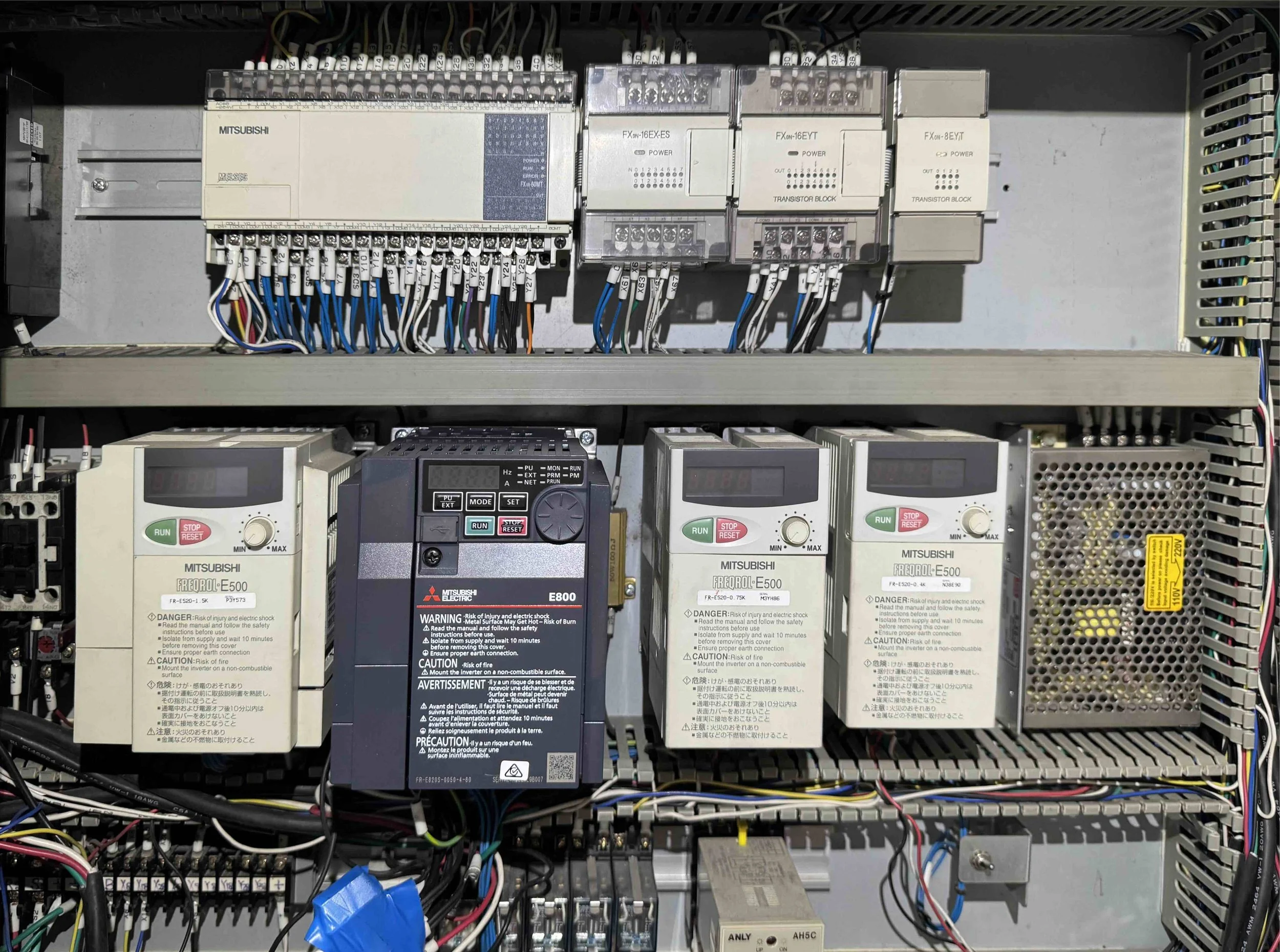
Control cabinet after the change — new Mitsubishi FR-E820S in the middle of the remaining FR-E500 units.
The infeed uses a Mitsubishi FR-E520-0.75K. Alarm history showed the same regenerative overvoltage trip four times: E.OV2 at 65 Hz, 2.41 A, 231 V, after 18 s. That snapshot looks like a brake or overhauling-load problem.
The brake resistor beside the inverter measured about 100 Ω and was wired correctly. While the fault was happening, the DC bus fell under 260 V rather than climbing into an overvoltage trip. That points at the DC bus capacitors, not the resistor. Phase-to-phase motor resistance was about 7 Ω, with no breakdown to earth.
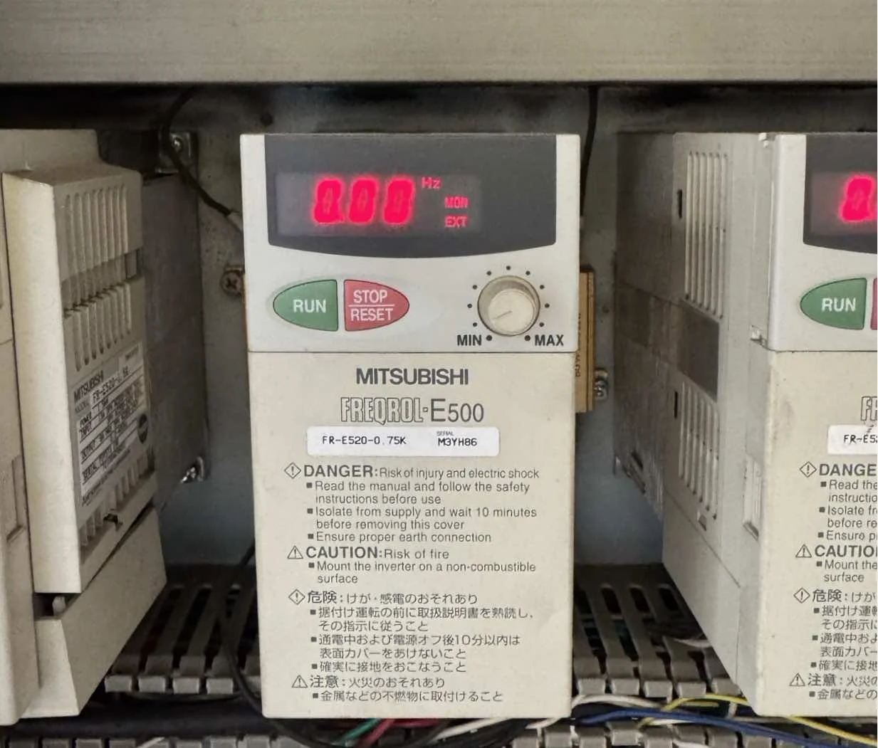
Original FR-E520-0.75K — control wires on SD, sink logic, PLC outputs on Y10–Y13
Replacement when the like-for-like part is months away
A like-for-like FR-E520 was only available as a build-to-order item, with a 16–18 week lead time. We fitted a Mitsubishi FR-E820S-0050-4-60 instead — single-phase 200–240 V in, 0.75 kW, 5.0 A — fed from the two supply legs the old drive was already using. A 3D printed mounting bracket took up the wider 108 mm body so the unit sat in the same place in the cabinet.
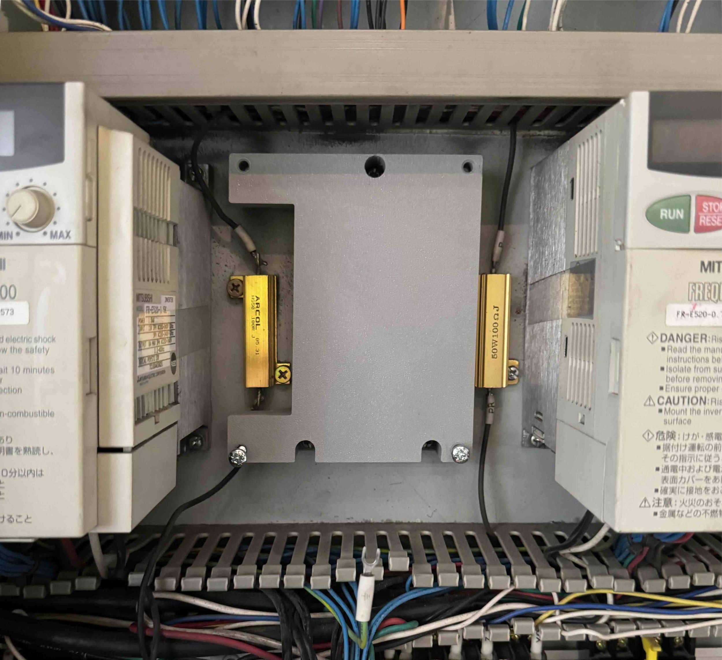
3D Printed mounts that the larger single phase drive can fit in the slot that the original 3 phase drive occupied.
Parameters came across from the E520. The PLC map stayed the same: Y13 forward (STF), Y10 reverse (STR), Y12 low speed (RL), Y11 middle speed (RM) and second acceleration/deceleration (RT on the MRS terminal).
The new drive ships as source logic. This machine’s FX outputs and the original wiring are sink. With the control-logic switch still on SOURCE, the keypad ran the motor but the PLC inputs did nothing. Setting the switch to SINK, with the power off, brought the I/O up. Pr. 183 was set to 3 so the MRS terminal became RT again.
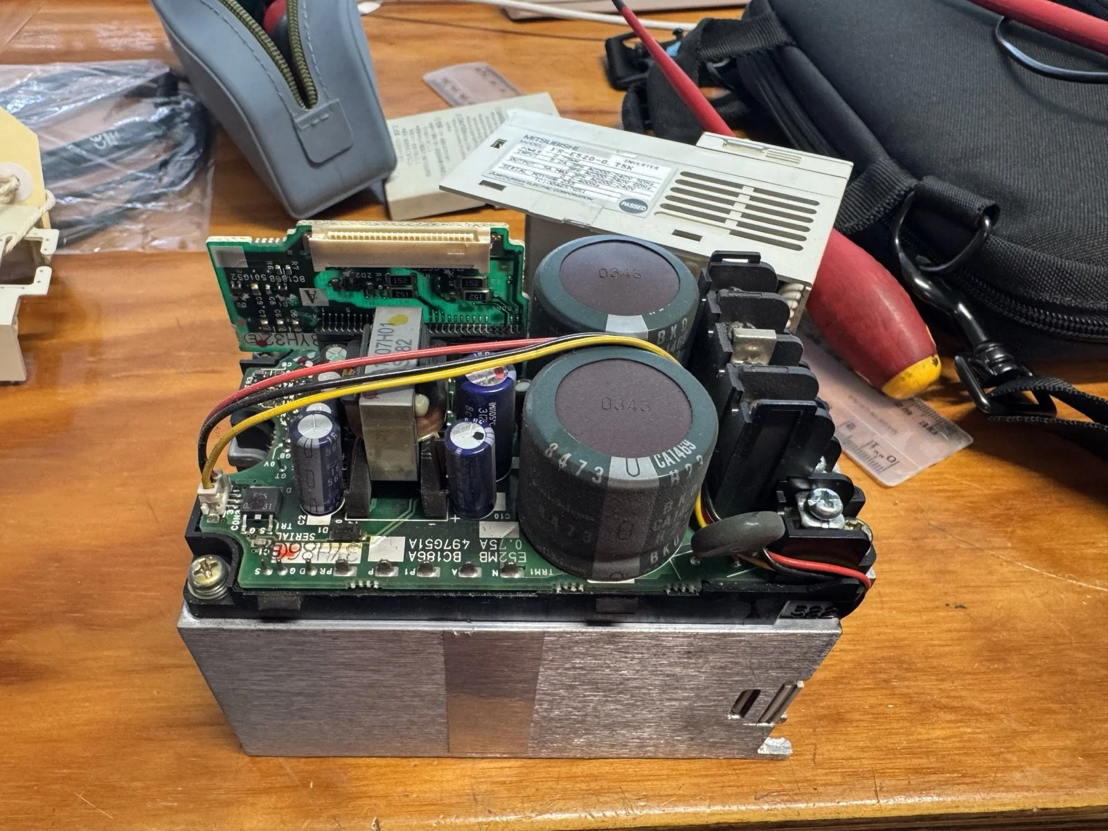
Opened FR-E520 on the bench. The large electrolytics are what the bus reading was pointing at.
Back in production
With sink logic and the second-ramp assignment in place, the infeed table ran under PLC control again. The machine was put through its paces on site and left ready for the next production job.
The jerky motion was not a worn infeed mechanism and it was not a brake resistor that had gone open. It was an ageing E500 power stage that could no longer hold the DC bus under load — replaced with a current E800-series drive that took the same PLC signals once the sink/source switch matched the cabinet.